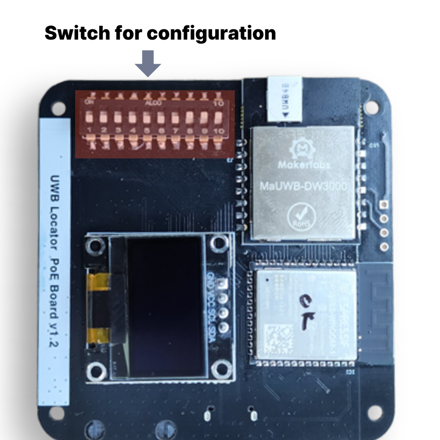
DIP Switch Configuration Guide
Mapping for the 10-position DIP switch on the ESP32-S3 UWB board. All settings are applied live while the board is powered (500 ms debounce, then STM32 reconfiguration).
1. Full mapping
| SW | GPIO | Function | ON (HIGH) | OFF (LOW) |
|---|---|---|---|---|
| SW1 | IO11 | index bit 0 (LSB) | +1 | 0 |
| SW2 | IO10 | index bit 1 | +2 | 0 |
| SW3 | IO9 | index bit 2 | +4 | 0 |
| SW4 | IO46 | index bit 3 | +8 | 0 |
| SW5 | IO3 | index bit 4 | +16 | 0 |
| SW6 | IO8 | index bit 5 (MSB) | +32 | 0 |
| SW7 | IO7 | data rate | 850 k | 6.8 M (default) |
| SW8 | IO6 | LAN (Ethernet) | enabled (DHCP + MQTT) | disabled (default) |
| SW9 | IO5 | Gateway mode | enabled | normal mode |
| SW10 | IO4 | role | Anchor | Tag |
Strapping pins
SW4 (IO46) and SW5 (IO3) are ESP32-S3 strapping pins. Their state at reset can affect boot mode and debug log output — if the board fails to boot, check these switch positions first.
Switches short to 3.3 V (no external pull-down). ESP32 internal pull-downs are enabled. ON = HIGH = 1.
2. Mode behaviour
Normal mode (SW9 OFF)
- On boot, listens to STM32-stored Role/Id/Rate for 2.5 s.
- Match → skip provisioning (fast boot).
- Mismatch → send
AT+SETCFG / SETCAP / SETRPT / SAVE / RESTART(~10 s). - On switch change → 500 ms debounce, then reconfigure (STM32 restarts).
- OLED:
A0 6.8M,T15 850k, etc. - If SW8 ON, ENC28J60 init + MQTT connect runs at end of boot.
Gateway mode (SW9 ON)
- No commands sent to STM32 (provisioning fully skipped).
- Pure passthrough: USB CDC ↔ UART2 +
AT+RANGE→ JSON. - SW1–SW6, SW7, SW10 are ignored (effective role/ID is whatever STM32 has saved).
- SW8 (LAN) still works in gateway mode — you can publish over MQTT while acting as a gateway.
- OLED:
Gateway. - Useful as a temporary boot-loop bypass since STM32 is never touched.
3. Index calculation (SW1–SW6)
Binary, SW1 = LSB:
| Desired idx | SW6 | SW5 | SW4 | SW3 | SW2 | SW1 |
|---|---|---|---|---|---|---|
| 0 | OFF | OFF | OFF | OFF | OFF | OFF |
| 1 | OFF | OFF | OFF | OFF | OFF | ON |
| 2 | OFF | OFF | OFF | OFF | ON | OFF |
| 3 | OFF | OFF | OFF | OFF | ON | ON |
| 5 | OFF | OFF | OFF | ON | OFF | ON |
| 10 | OFF | OFF | ON | OFF | ON | OFF |
| 16 | OFF | ON | OFF | OFF | OFF | OFF |
| 32 | ON | OFF | OFF | OFF | OFF | OFF |
| 63 | ON | ON | ON | ON | ON | ON |
Range: 0 – 63 (matches UWB_TAG_COUNT = 64).
4. Data rate (SW7)
DW3000 UWB data rate. Both the AT+SETCFG freq bit and the AT+SETCAP slot time
change together.
| SW7 | Rate | Slot | Trade-off |
|---|---|---|---|
| OFF | 6.8 M | 10 ms | Short packets, higher throughput, slightly shorter range |
| ON | 850 k | 15 ms | Longer packets (stronger sync), longer range, more noise tolerance |
4-1. LAN / MQTT (SW8)
Toggle for the ENC28J60 + MQTT publish stack.
| SW8 | Behaviour |
|---|---|
| OFF | LAN disabled. Same as the original behaviour (USB serial + OLED + UART passthrough only). |
| ON | At boot, init ENC28J60 → DHCP → connect to broker.hivemq.com:1883. JSON built from AT+RANGE is published to topic uwb/range/{A\|T}{idx}. |
Pinout (ENC28J60-I/ML)
| Signal | GPIO |
|---|---|
| LAN_SPI_MOSI | IO13 |
| LAN_SPI_MISO | IO14 |
| LAN_SPI_SCLK | IO21 |
| LAN_INT | IO47 |
| LAN_SPI_CE | IO48 |
MQTT topic / payload
- Topic:
uwb/range/A0,uwb/range/T5, etc. (role + idx) - Client ID:
uwb-A0-XXXXXX(last 3 bytes of eFuse MAC) - Payload (example):
{"id":3,"range":[1234,1280,1310,...]}— same JSON as the serial log.
OLED display
With SW8 ON, the line below the version banner shows persistent LAN status:
LAN ...— DHCP in progressL 192.168.1.5— link OK / MQTT not connectedM 192.168.1.5— MQTT connected (publishing)
SW8 is read at boot only. Toggling at runtime does not bring LAN back up — reboot.
5. Common configurations
Anchor 0 @ 6.8 M (typical reference anchor)
- SW10 ON, others OFF
- Display:
A0 6.8M
Anchor 5 @ 6.8 M
- SW10 ON
- SW1 ON, SW3 ON (= bit0 + bit2 = 5)
- Display:
A5 6.8M
Tag 0 @ 6.8 M
- All OFF (or SW10 OFF + idx 0)
- Display:
T0 6.8M
Tag 10 @ 850 k (long range)
- SW10 OFF
- SW2 ON, SW4 ON (= bit1 + bit3 = 10)
- SW7 ON
- Display:
T10 850k
PC gateway (receive JSON over USB)
- SW9 ON (other switches don't matter)
- Display:
Gateway
6. Serial diagnostics
Every 2 s after boot, the following line is emitted (in addition to the OLED):
In gateway mode, prefixed with GW:
Right after a switch change, additionally:
7. Caveats
- Boot loop: switch SW9 ON to enter gateway mode — ESP32 stops touching the
STM32, so the loop ends. Use the serial log to read the STM32's current state
(
Role:Anc, Id:0, Rate:6.8M, etc.). - Strapping pins SW4 (IO46), SW5 (IO3): their state at reset affects ESP32 boot mode. Keep them OFF during flashing.
- STM32 restart on provisioning: changing SW10/SW7 or any index bit triggers
an
AT+RESTARTon the STM32. Ranging data is interrupted for ~5–10 s. - 3.3 V decoupling: when running multiple boards together, STM32 flash writes and UWB TX spikes can brown out the ESP32 (POWERON reset). Add ≥ 100 µF on the 3.3 V rail.
8. GPIO summary
| GPIO | Use |
|---|---|
| 3, 4, 5, 6, 7, 8, 9, 10, 11, 46 | DIP SW1–SW10 (reverse order) |
| 13 | LAN_SPI_MOSI (ENC28J60) |
| 14 | LAN_SPI_MISO (ENC28J60) |
| 16 | STM32 RESET (active-low, held HIGH) |
| 17 | UART2 TXD → STM32 |
| 18 | UART2 RXD ← STM32 |
| 21 | LAN_SPI_SCLK (ENC28J60) |
| 38 | I²C SCL (OLED) |
| 39 | I²C SDA (OLED) |
| 43, 44 | UART0 TX/RX (USB-UART bridge, serial log) |
| 47 | LAN_INT (ENC28J60) |
| 48 | LAN_SPI_CE (ENC28J60) |